Ballspinner Physical Design
Physical System
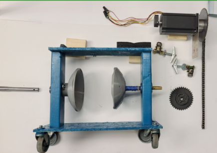 |
- Exploded View of the Physical Model:
- 2x 2”x4”x36” wood blocks used to support the ball and house the bearings
- 2x plywood pieces to mount motor and serve as base
- 1x steel axle rod 0.8” OD ± 0.01”
- Extra material serves as minor counterweight
- Axle rod to be threaded for vice handle and lock nut clamping mechanism (future Implementation)
- 1x 34Y307D-LW8 NEMA 34 stepper motor w/ a E5-500-394-I-D D-G-B motor encoder mounted onto the rear
- Mounted using aluminum faceplates that screw into the wood block faces
- Resting on top vibration dampening, foam, material
- Utilizes a padded shim to offset motor tilt
- 3-D printed cups are sized to house the foam ball and hold it in place using screws
- The physical model is constructed using two pieces of wood measuring 3.5”x1.5”x36” and two plywood pieces to serve as base and motor mount. The vice axle (left) side is made using a steel rod machined down to 0.8” OD ± 0.01” so as to fit within the single bearing mounted within the vice axle side. The extra length of the axle rod serves as a minor counterweight and will be threaded to mount a vice handle lock nut system, future implementation, this axle feeds through the bearing and into the cup which it is then locked into. The motor on top is a 34Y307D-LW8 NEMA 34 stepper motor with a E5-500-394-I-D-D-G-B encoder mounted onto the rear. The motor rests on a piece of dampening material (foam) and is mounted to the system by using an aluminum face-plate which is screwed onto the system and face of the motor. The motor is geared using a 1.25:1 ratio and connected to the motor axle via chain, which is held taught by chain tensioners mounted below the face plate. The motor axle is constructed using a dowel rod that was sanded and modified to fit the bearings that are both mounted within the motor side of the system.
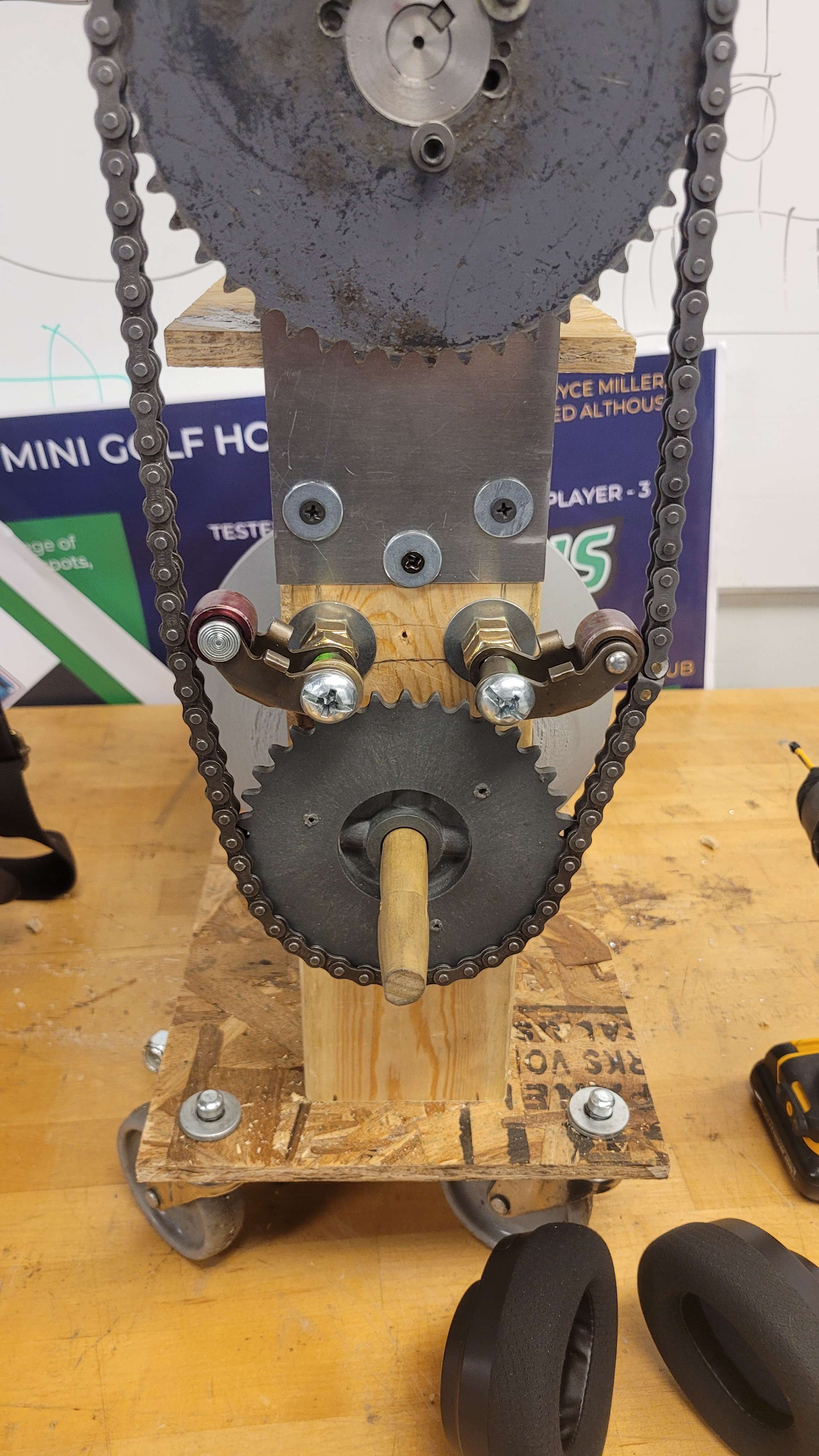 |
- Side View of the Physical Model Showing the Chain Assembly: The exposed chain measures around 40” in length when unlinked and connects a 6” OD 3 teeth/inch spur gear to a ~4.8” OD 3 teeth/inch spur gear. This results in a 1.25:1 gearing ratio that is driven via the stepper motor. Chain tensioners are implemented to keep the chain action smooth and consistent, especially since this axis will experience the highest level of rotation and is not currently guarded outside of the enclosure.
 |
-
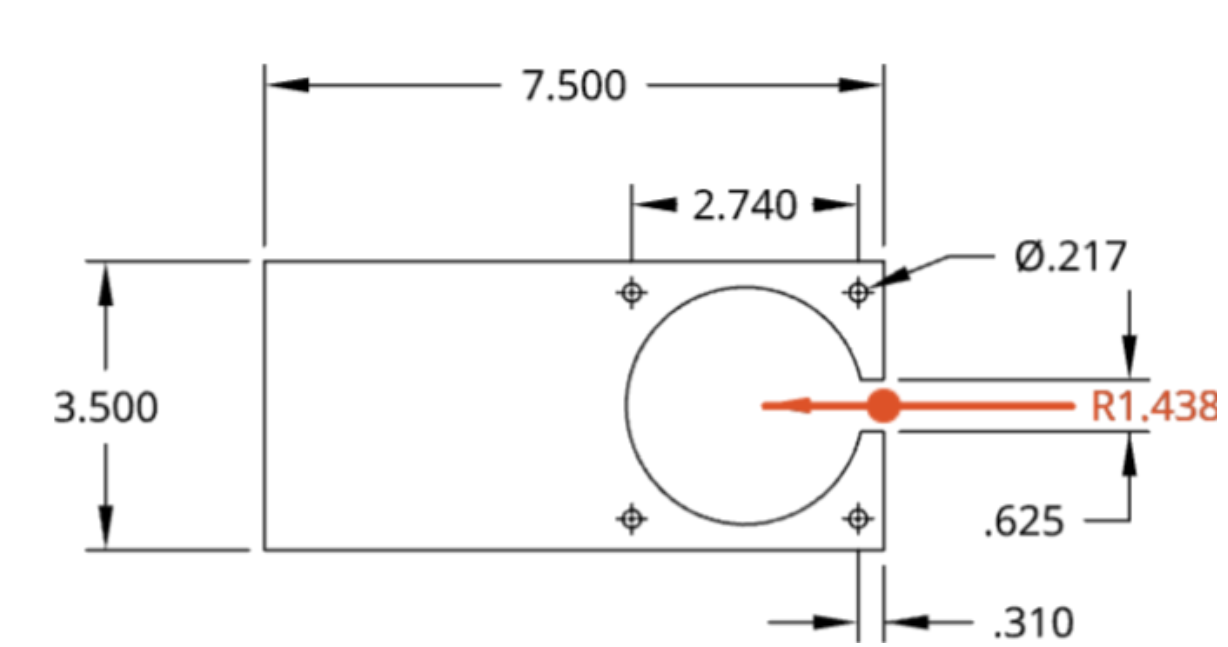
Motor Mounting Plate:
- 3 ½” by 7 ½” aluminum plate
- Four small through holes with a 0.217 inch diameter (through holes for screwing into face of motor)
- Each through hole is spaced 2.740 inches apart
- The radius of the large through hole is 1.438 inches (fits snugly around the notch of the motor)
-
The primary purpose of the motor mounting plate is to securely hold the motor steady in place preventing any lateral movement during operation. The motor mounting plate is screwed into the face of the motor and into the 2x 2”x4”x36” wood blocks. The Motor Mounting Plate is made out of an 6061 T6 aluminum plate with a thickness of ⅛”.
-
Manufacturing Process for Motor Mounting Plate:
The machine used to manufacture the Motor Mounting Plate was the water jet cutter (Insert name of model). In order to manufacture a piece on the water jet cutter you must follow the steps below. (After part has been created)
- Export to DXF file
- Select file
- Select Export to DXF/DWF
- Save file (make sure you are in the correct units)
- Upload DXF file to a USB drive
- Insert USB drive into Dell laptop for the water jet cutter
- Select ProtoMax Layout
- Select ProtoMax Make
- Import your Layout file from Promax Layout
- Select autopath
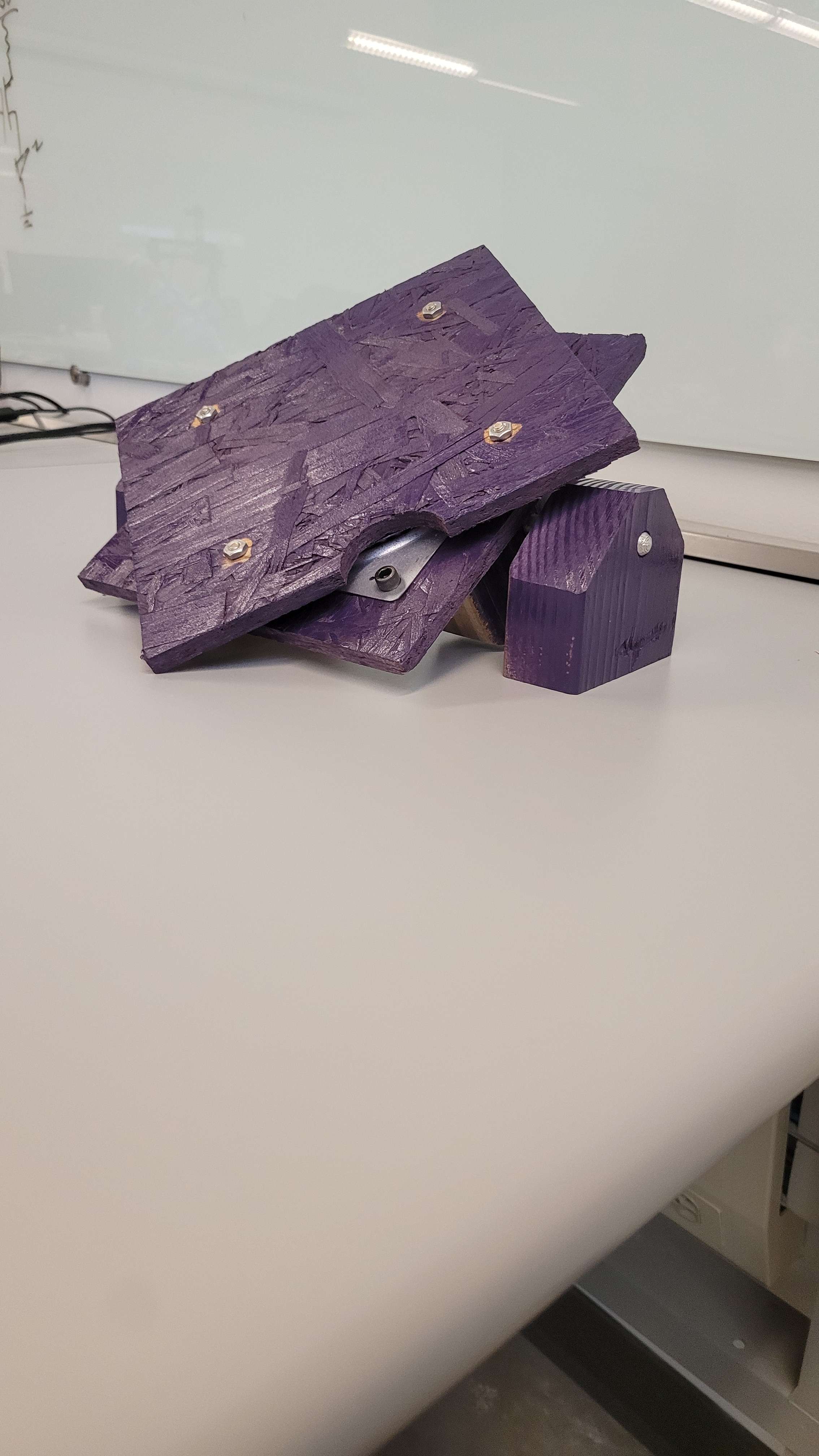 |
- Pitch and Yaw Rotation Model: This miniaturized model was intended to demonstrate the methods by which the model will need to rotate as well as for our team to visualize how to motorize them. For the top (Yaw) plate, the team was looking to motorize the system through a direct drive pancake motor seated underneath the bottom plate, which is connected to the top plate through a “lazy susan”, and through the central hole of the “lazy susan” to drive the top plate. The side (Pitch) legs house an axle that allows for rotation freely and angled cuts set to 45°. This side would be motorized through rotation of the axle or some equivalent method.
- Model Representation of Vice Axle Mounting Mechanism: A model that depicts the method by which the steel axle rod was intended to be threaded to allow for clamping and withdrawal of the cup from the ball to facilitate no-slip rotation as well as removal/replacement of the ball if necessary or desired.
Proposed System
1st Axis
Relies on a vice grip system with lock nuts to induce a clamping force to prevent slippage.
Driven by gear and chain
2nd Axis
Rotates the previous sub-system utilizing a direct drive motor paired with a lazy susan to pivot up to 90 degrees in either lateral direction
3rd Axis
Directly driven to tilt the previous sub-systems up to 45 degrees in either direction.
Bowling Ball Insert
The insert will allow the SmartDot chip to remain in the bowling ball securely as it spins. It must hold the chip at the right depth of the bowling ball while having clear view for the light sensor on the chip.
Target numbers
The goal for the primary axis of rotation is 750 RPM while the secondary axis needs 10 RPM and the third axis only need 2.5 RPM. For a 16 lbs bowling the vice would need a clamping force of only 35 lbs.


