Ballspinner Physical Design
Physical System
 |
|---|
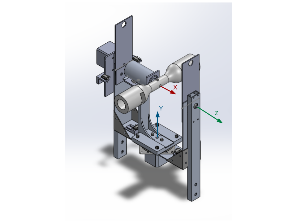
The Ball Spinner Mechanical system is used to simulate real bowling data by rotating a ball analog in all three degrees of freedom. Each degree of freedom will be controlled by the Ball Spinner Controller. The first degree of freedom is about the x-axis, which rotates the SmartDot Holder. The second degree of freedom system will control the rotation about the y axis, and will hold the first system on a rotating platform. The third degree of freedom is the z-axis rotation of the previous systems. This design places all three axes of rotation so that they intersect at the center of the simulated bowling ball to ensure that collected data is consistent with real-world motion. The system should be able to perform the instructions provided by the Ball Spinner Controller, and the data collected should be analogous to data that would be collected from a SmartDot inside an actual bowling ball as it is thrown down a lane.
SmartDot Holder
 |
|---|
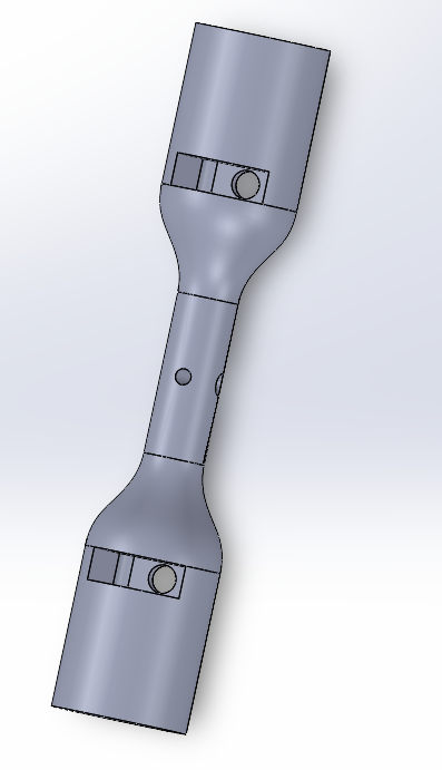
The SmartDot holder is mounted on the first degree of freedom motor and houses the SmartDot sensors. The design was made to be 8.5 inches long to accurately model the diameter of an actual bowling ball. At both ends of the SmartDot holder, a SmartDot will be housed via friction fit. The SmartDots are inserted perpendicularly to the direction of rotation, minimizing the ability of rotational effects to dislodge them. Opposite the SmartDot slots are holes to allow the SmartDot module to be pushed out to allow for easy exchange. This SmartDot holder was designed with weight as a critical factor to reduce the required torque from all motors. The design features press fit finger inserts holes above the SmartDot slots and a hole located 90 degrees from the shaft hole to allow for set screw placement.
3 Degree of Freedom System
 |
|---|
The ball spinner design is based around aluminum as the primary material because of its accessibility and ease of manufacturing. Where necessary, some parts are 3D printed, such as motor and limit switch mounts and the SmartDot Holder, to avoid excess time spent machining complex parts. Parts for the model were primarily selected from the McMaster-Carr catalogue. The third degree motor is mounted to the U-bracket via a shaft collar with face mounts. This ensures a much more stable connection between the motor and the center assembly. The final design also features a redesigned L-bracket, which was fabricated out of an aluminum block. The L-bracket features gussets that were included in the profile of the wire EDM profile cut. The U-bracket also contains gussets which are bolted onto the plate. Reinforcements on both of these pieces help to reduce vibration. The model also incorporates a counterweight system. These extensions mount directly onto the insides of the U-bracket and have holes located at the top of the plate to mount bolts with brass weights. This was done to improve the balance of the third degree and shift the center of mass of the U-bracket closer to the 3rd degree motor shaft.
Ball Spinner Controller Enclosure
 |
|---|
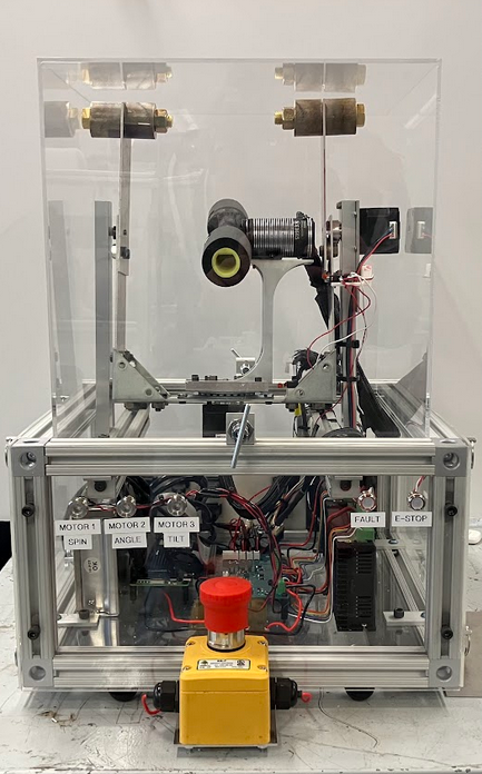
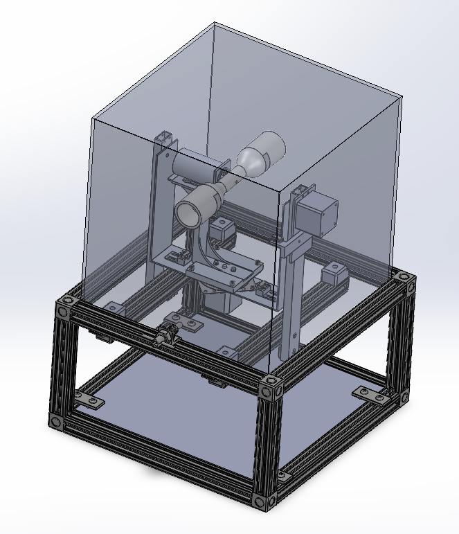
To prevent injury, a clear acrylic cover was mounted to obstruct access to the system during operation. The box is elevated using 3D printed supports at each corner to allow room for wires and electrical hardware. The acrylic case also contains holes to allow for T-handle spring plungers which keep the acrylic in place during a collision with moving components. With the integration of the Ball Spinner Controller into the Ball Spinner Mechanical System, there was a need to house all of the electrical hardware which would be located close to the 3DOF mechanical system. The platform enclosure is a 14”x14” box with removable top and side panels and interior space for the Ball Spinner Controller Team’s equipment, such as the power supply, motor drivers, and raspberry pi. The enclosure is made with aluminum T-slotted channels, bolts, and sliding nuts to allow for easy mounting and repositioning of parts. This design allows the third degree supports of the physical system to be mounted directly to the frame. The enclosure is also equipped with acrylic side panels to allow visibility for all of the electrical components within. The side acrylic panels are pin mounted while the front and back are mounted through bolts and sliding nuts. The back of the enclosure features a 3D printed back plate to allow for connecting various ports to the system. Located at the bottom of the enclosure is a polycarbonate sheet which holds all of the electrical components. The enclosure rests on top of eight total rubber feet to help prevent movement of the enclosure while the ball spinner is in motion. Finally, a plate was mounted to the underside of the front lower channel to provide a support plate for the system’s emergency stop button.
Printing and Bending
For 3D printing polycarbonate, the best results were achieved with print head temperature at 260 C, print bed temperature at 110 C, fan speed at 0%, and speed at 1100 mm/min within an enclosed printer. For the Prusa mk3, crash detection must be turned off at a high bed temperature. Additionally, research into setting enclosure temperature to a specific value should be conducted.
To bend aluminum sheet without cracking, the aluminum should be annealed. One method to do this is marking the part with Sharpie marker and heating with a propane torch until the Sharpie mark disappears, and then leaving to air cool. The part should then be bent at a given radius to prevent a sharp internal bend. The physical team used 3D printed parts that fit onto the sheet metal bender in the shop.
Specs
The first degree motor will need to accelerate to 600 rpm in 150 milliseconds.
The second degree motor rotates up to 45 degrees in each direction within one second.
The third degree motor rotates up to 22.5 degrees in both directions in less than a second.